Product Description
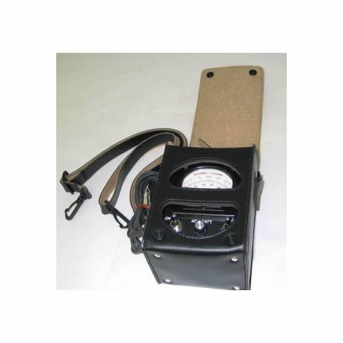
Triplett 3072 Brownie Meter W/Case 8455L1 W/O Battery New The Simpson 8455 Line Loop Testers (Hereafter Referred To As The 8455 Or The
Instrument) Were Specifically Designed To Analyze Telephone Line Faults. Compact,
Rugged, And Easy-To-Use, They Are Capable Of Measuring Dc Voltage To 100
Volts And Loop Resistances To 2M� (8455 V3) Or 10K� (8455A). The Voltmeter
Function Can Be Used To Detect And Measure Any Dc Voltage On The Line And The
Resistance Ranges Can Be Used To Identify And Locate Line Faults.
The Meter Is Of Pivot-And-Jewel Construction With A 2-3/8" Diameter Dial With Knifeedge
Pointer That Moves Across A 2-3/16" (100�) Scale Arc. Scales Are As Follows:
Points: 0-100 For Ballistic Tests
M�-K�: (8455 V3) 0-2M� Or 0-200K� Ranges; 0-10K� (8455A)
Voltage: 0-100 Points = 0-100V
Due To The 0-100� Scale Arc And The 0-100 Dial Calibrations, The Accuracies Of
�2% Of Full Scale And �2� Of Scale Arc Are Both Represented By �1 Scale Division Of
The Points Scale Anywhere On The Scale.
The 8455A Differs From The 8455 V3 In That It Substitutes A 0-10K� Range For The 0-
200K� Range Of The 8455 V3. The 2M� Range Remains For Points Measurements,
But Does Not Have A Separate Meter Dial Scale.
The 8455 V3 Differs From Earlier 8455 In That It Incorporates A Field Replaceable
Switch Design. The 8455A Shares The Field Replaceable Switch Design.
Throughout This Manual, �8455� Will Now Refer To Both The 8455 V3 And The 8455A,
Unless Otherwise Noted.
Items And Accessories Furnished With This Instrument
Quantity Description Number
1 Test Lead Set 45001
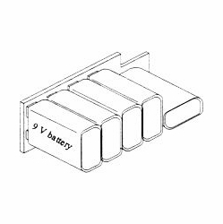
1 Battery, 45V, Neda, Type 201 6-113313
1 Operator�S Manual 6-115458
1 Carrying Case 00836
Table 2-2. Other Available Accessories
Description Number
Carrying Case, Leatherette M00674
Extra Test Lead Set 45001
Replacement Toggle Switch Boards (Set Of 10) 45025
Replacement Push-Button �Reverse� Switch Boards (Set Of 10) 45026
Test Leads
The Test Lead Set Consists Of One Each, Red And Black, Flexible Test Leads, 6 Feet
Long With Telco Clips At One End And Ring-Tongue Connectors At The Other End For
Connection To The Instrument�S Screw Terminals.Read More
 Warning: This product can expose you to chemicals, which are known to the State of California to cause cancer and birth defects or other reproductive harm. For more information, go to www.P65Warnings.ca.gov


