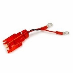
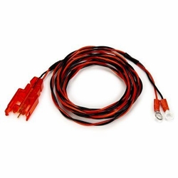
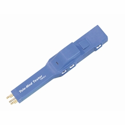
Circa Tmtc1 Tele-Mod Tester ( )
Available*
Item # 20330125
Model # 841005
$126.37
* Notes on Availability:
If item is in stock, it will ship same day.
Lead times vary, contact us for more info.
(Images may not be of the actual item being sold.)
- Product Description
- You Might Also like
- Recently Viewed
Generic
Class
Group
Type
Manufacturer
LOT
Frame Cord
Test Equipment
Leads- Cords- Clips
Cords- Test Set- Specialty
Circa Telecom USA Inc
 Warning: This product can expose you to chemicals, which are known to the State of California to cause cancer and birth defects or other reproductive harm. For more information, go to www.P65Warnings.ca.gov
Product Description
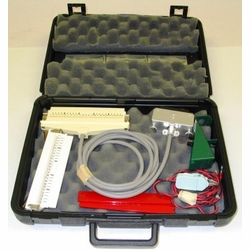
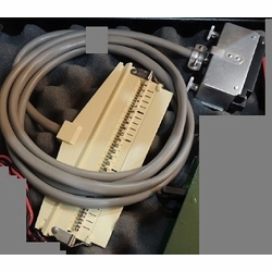
Circa Telecom Tmtc1 Tele-Mod Tester (New) In Seconds, Look Into The Central Office Or Out To The Field. Access Cable Pairs
By Plugging Into Any 5-Pin Connector Block Located At The Building Entrance.
To Troubleshoot - Simply Clip A Buttset Or Voltmeter To The Metal Tabs Marked “Tip”
And “Ring” In And Look To The Switch. Move The Clips To The Tabs Marked “Tip” And
“Ring” Out And Look To The Field. To Restore Temporary Service To The Customer While Troubleshooting, Simply
Plug In An Osp Kit Modular-Looping Tool.
Adding A Protector Module To The Tele-Mod Tester Enables Access To The Central Office’S Wiring.
1. When The Protector Is Plugged In:
A. The Test/Light Switch Lights A Red Or Green Led Depending On The State Of The Protector.
It Glows Green If The Protector Is Good, Red If The Protector Is Bad.
B. The Detector Directs The Looking-In (Central Office) Lines Through The Protector.
C. The Short Pins Looking-In (Co) Are Protected.
D. The Long Pins Looking-Out (Field) Are Unprotected.
E. Looking-In (Co) And Looking-Out (Field) Are Tested Independently.
2. Plug In An Rj11 To The Tele-Mod Tester:
A. Rj11 Looping Plug: The Field Lines Are Connected To The
Looking-In (Co) Lines And The Phone Line Becomes Protected.
B. Rj11 To The L4 Cord: Makes A Protected
“Good Shoe / Bad Shoe” Cord.
C. Rj11 To Rj11 Jumper Cord: Protects
The Looking-In (Co) Side.
D. Rj11: Tests The Unit In Both Directions Independently.
3. The White Led Flashlight Aids In Locating Target Area.


